This chapter describes the general components, characteristics, ammunition, and accessories for the M16- and M4-series weapons to include a brief explanation of how to mount the various accessories.
The M16-/M4-series weapons are 5.56-mm, magazine-fed, gas-operated, air-cooled, shoulder-fired weapons. This section describes the general characteristics (Table 2-1) and the components of the M16-/M4-series weapons. Table 2-2 shows the characteristics of various accessories.
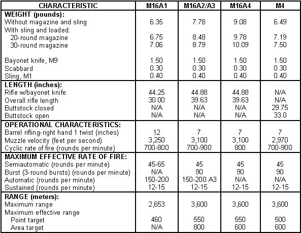
Table 2-1. Characteristics of the M16-/M4-series weapons.
|
NOTE: |
For further technical information, refer to TM 9-1005-319-10 and TM 9-1005-249-10. |
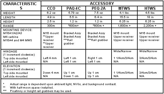
Table 2-2. Characteristics of various accessories
for the M16-/M4-series weapons.
|
NOTE: |
For further technical information on these accessories refer to TM 9-1240-413-12&P (CCO), TM 11-5855-301-12&P (PAQ-4B/C), TM 11-5855-308-12&P (PEQ-2A) and TM 11-5855-302-12&P (TWS) |
a. The M16A1 (Figure 2-1) can be fired in either the semiautomatic or automatic fire mode by rotating the selector lever to the desired mode (SAFE, SEMI, and AUTO).
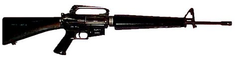
Figure 2-1. M16A1 rifle.
(1) Mechanically Zeroing the M16A1. Mechanically zeroing the M16A1 (Figure 2-2) is only necessary when the weapon zero is questionable, the weapon is newly assigned to the unit, or the weapon sights have been serviced. If necessary, the soldier should mechanically zero the weapon as follows:
(a) Adjust the front sight post (1) up or down until the base of the front sight post is flush with the front sight post housing (2). Then adjust the front sight post 11 clicks in the direction of UP.
(b) Adjust the rear sight windage drum (3) all the way left until it stops. Then turn the windage drum back (right) 17 clicks so the rear sight is approximately centered.
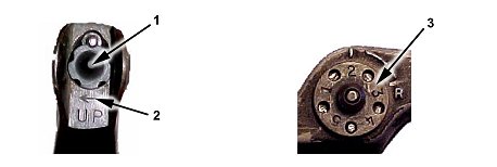
Figure 2-2. M16A1 rifle mechanical zero.
(2) Battlesight Zeroing the M16A1. If necessary, the soldier should use the aperture marked "L" to battlesight zero the weapon (Figure 2-3). Tables 2-3 and 2-4 show how much one click of elevation or windage will move the strike of the round from a 25-meter zero all the way out to 500 meters.
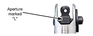
Figure 2-3. M16A1 rifle battlesight zero.
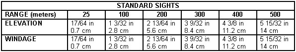
Table 2-3. Point of impact for M16A1 with standard sights.
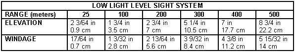
Table 2-4. Point of impact for M16A1 with LLLSS.
b. The M16A2/A3 rifle (Figure 2-4) features several improvements over the M16A1. It is designed to fire either semiautomatic or a three-round burst through the use of a selector lever (SAFE, SEMI, and BURST). The M16A3 has the same characteristics as the M16A2 with the exception of the selector lever (SAFE, SEMI and AUTO) this weapon fires full automatic.
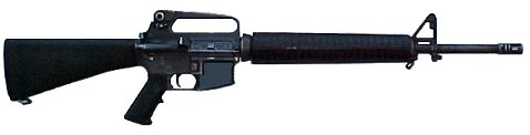
Figure 2-4. M16A2/A3 rifle.
(1) Mechanically Zeroing the M16A2/A3. Mechanically zeroing the weapon (Figure 2-5) is only necessary when the weapon zero is questionable, the weapon is newly assigned to the unit, or the weapon sights have been serviced. If necessary, the soldier should mechanically zero the weapon as follows:
(a) Adjust the front sight post (1) up or down until the base of the front sight post is flush with the front sight post housing (2).
(b) Adjust the elevation knob (3) counterclockwise, as viewed from above, until the rear sight assembly (4) rests flush with the carrying handle and the 8/3 marking is aligned with the index line on the left side of the carrying handle.
(c) Position the apertures (5) so the unmarked aperture is up and the 0-200 meter aperture is down. Rotate the windage knob (6) to align the index mark on the 0-200 meter aperture with the long center index line on the rear sight assembly.
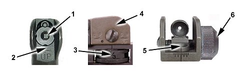
Figure 2-5. M16A2/A3 rifle mechanical zero.
(2) Battlesight Zero the M16A2/A3. If necessary, the soldier should battlesight zero the weapon as follows (Figure 2-6):
(a) Adjust the elevation knob (1) counterclockwise, as viewed from above, until the rear sight assembly (2) rests flush with the carrying handle and the 8/3 marking is aligned with the index line (3) on the left side of the carrying handle. Then adjust the elevation knob one more click clockwise.
(b) Position the apertures (4) so the unmarked aperture is up and the 0-200 meter aperture is down. Rotate the windage knob (5) to align the index mark on the 0-200 meter aperture with the long center index line on the rear sight assembly.
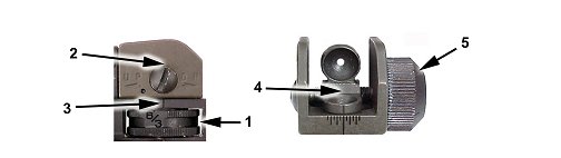
Figure 2-6. M16A2/A3 rifle battlesight zero.
(c) Table 2-5 shows how much one click of elevation or windage will move the strike of the round from a 25-meter zero all the way out to 600 meters.

Table 2-5. Point of impact for M16A2/A3.
c. The M16A4 rifle (Figure 2-7) features additional product improvements that are illustrated in this chapter and in the operator's manual. It is designed to fire either semiautomatic or a three-round burst through the use of a selector lever (SAFE, SEMI, and BURST). The only changes from the M16A1/A2/A3 are the addition of the M5 rail adapter system and the detachable carrying handle.
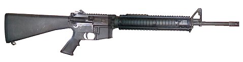
Figure 2-7. M16A4 MWS.
(1) Mechanically Zeroing the M16A4. Mechanically zeroing the weapon is only necessary when the weapon zero is questionable, the weapon is newly assigned to the unit, or the weapon sights have been serviced. If necessary, the soldier should mechanically zero the weapon as follows (Figure 2-8):
(a) Adjust the front sight post (1) up or down until the base of the front sight post is flush with the front sight post housing (2).
(b) Adjust the elevation knob (3) counterclockwise, when viewed from above, until the rear sight assembly (4) rests flush with the carrying handle and the 6/3 marking is aligned with the index line (5) on the left side of the carrying handle.
(c) Position the apertures (6) so the unmarked aperture is up and the 0-200 meter aperture is down. Rotate the windage knob (7) to align the index mark on the 0-200 meter aperture with the long center index line (8) on the rear sight assembly.
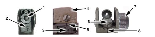
Figure 2-8. M16A4 MWS mechanical zero.
(2) Battlesight Zero the M16A4 MWS. If necessary, the soldier should battlesight zero the weapon as follows (Figure 2-9):
(a) Adjust the elevation knob (1) counterclockwise, when viewed from above, until the rear sight assembly (2) rests flush with the detachable carrying handle and the 6/3 marking is aligned with the index line (3) on the left side of the detachable carrying handle. To finish the procedure, adjust the elevation knob two clicks clockwise so the index line on the left side of the detachable carrying handle is aligned with the "Z" on the elevation knob.
(b) Position the apertures (4) so the unmarked aperture is up and the 0-200 meter aperture is down. Rotate the windage knob (5) to align the index mark on the 0-200 meter aperture with the long center index line (6) on the rear sight assembly.
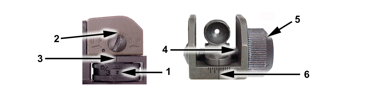
Figure 2-9. M16A4 MWS battlesight zero.
(c) Table 2-6 shows how much one click of elevation or windage will move the strike of the round from a 25-meter zero all the way out to 600 meters.
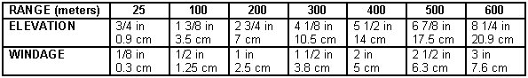
Table 2-6. Point of impact for M16A4 MWS.
d. The M4-series carbine (Figure 2-10) features several modifications that make it an ideal weapon for close combat operations. The M4 is a 5.56-mm, magazine-fed, gas-operated, shoulder-fired weapon. It is designed to fire either semiautomatic or a three-round burst through the use of a selector lever (SAFE, SEMI, and BURST). The M4A1 is fully automatic. The M4-series carbine buttstock has four positions: closed, 1/2 open, 3/4 open, and full open. The M4 carbine becomes the M4 MWS when the M4 rail adapter system is installed on it (Figure 2-11).
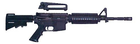
Figure 2-10. M4/M4A1 carbine with standard handguards installed.
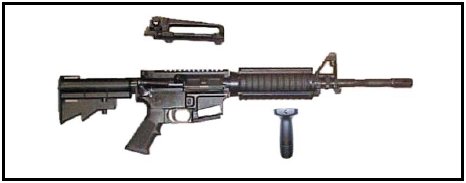
Figure 2-11. M4 MWS.
(1) Mechanically Zeroing the M4/M4A1 and M4 MWS. Mechanically zeroing the weapon is only necessary when the weapon zero is questionable, the weapon is newly assigned to the unit, or the weapon sights have been serviced. If necessary, the soldier should mechanically zero the weapon as follows (Figure 2-12):
(a) Adjust the front sight post (1) up or down until the base of the front sight post is flush with the front sight post housing (2).
(b) Adjust the elevation knob (3) counterclockwise, when viewed from above, until the rear sight assembly (4) rests flush with the detachable carrying handle and the 6/3 marking is aligned with the index line (5) on the left side of the carrying handle.
(c) Position the apertures (6) so the unmarked aperture is up and the 0-200 meter aperture is down. Rotate the windage knob (7) to align the index mark (8) on the 0-200 meter aperture with the long center index line on the rear sight assembly.
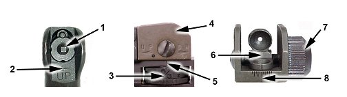
Figure 2-12. M4/M4A1 and M4 MWS mechanical zero.
(2) Battlesight Zero the M4/M4A1 and M4 MWS. If necessary, the soldier should battlesight zero the weapon as follows (Figure 2-13):
(a) Adjust the elevation knob (1) counterclockwise, when viewed from above, until the rear sight assembly (2) rests flush with the detachable carrying handle and the 6/3 marking is aligned with the index line (3) on the left side of the detachable carrying handle. The elevation knob remains flush.
(b) Position the apertures (4) so the unmarked aperture is up and the 0-200 meter aperture is down. Rotate the windage knob (5) to align the index mark (6) on the 0-200 meter aperture with the long center index line on the rear sight assembly.
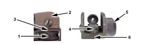
Figure 2-13. M4/M4A1 and M4 MWS battlesight zero.
|
NOTE: |
The "Z" marking on the elevation knob used in the detachable carrying handle of the M4-series weapon should be ignored. The "Z" marking is only used when the M16A4 is being zeroed. |
(c) Table 2-7 shows how much one click of elevation or windage will move the strike of the round from a 25-meter zero all the way out to 500 meters.
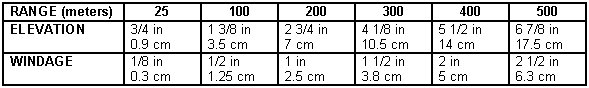
Table 2-7. Point of impact for M4/M4A1 and M4 MWS.
The M4 rail adapter system (RAS) (Figure 2-14) consists of a set of lightweight sections that replace the standard handguards on the M4 carbine. The M5 RAS is standard issue on the M16A4. The RAS provides a secure mounting point for various accessories that may be mounted top, left and right. The user may only remove the lower assembly to perform preventive maintenance checks and services (PMCS). Accessories may be mounted on the right side of the RAS but, currently, are not supported with 10- and 25-meter zeroing procedures. Only accessories that do not require retention, such as a flashlight or vertical pistol grip, can be mounted on the bottom rail.
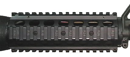
Figure 2-14. Rail adapter system.
|
NOTE: |
The bottom rail of the RAS will not retain zero. |
a. The RAS rail covers/heat shields can be quickly attached and detached from the RAS. A spring latch at one end of each rail cover/heat shield automatically engages cutouts in the RAS. To slide the shield beyond a cutout, or to remove it, apply thumb pressure to the center of the spring latch and slide it in the desired direction. The rail cover/heat shield protects the shooter's hands from direct contact with the metal parts of the RAS and protects the RAS surfaces from excess wear and damage. The M5 RAS rail covers/heat shields are available in 11-, 9-, 6-, 5-, and 4-rib sections (Figure 2-15).
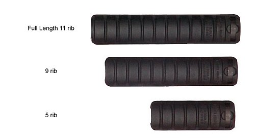
Figure 2-15. M5 rail covers/heat shields.
|
NOTES: |
1. Keep the bottom, left, and right unused rail sections covered with full-length 11-rib rail cover/heat shield sections. If any accessories are mounted on a rail, cover the remaining rail surface with an appropriately sized rail cover/heat shield. The top full length rail cover/heat shield will be permanently removed if a backup iron sight is installed and replaced with a shorter rail cover/heat shield to protect the firer's nonfiring hand when the barrel is hot. |
|
2. For ease of reference the shorter lengths can be referred to by the number of ribs along their outer surfaces. |
b. The even numbered recoil grooves of each rail of the RAS are sequentially numbered within the recoil grooves themselves (Figure 2-16). Each number is preceded by a letter prefix indicating a specific slot on the RAS. The numbers of the top rail have a "T" prefix while those of the bottom rail have a "B" prefix. Additionally, the numbers of the rail to the shooter's left have an "L" prefix while those on the rail to the shooter's right have an "R" prefix. These addresses assist the user in remounting an accessory in the same position, allows standardization on precisely where to mount certain accessories, and identifies reference points for discussions on accessory mounting locations.
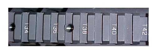
Figure 2-16. Address markings on RAS.
|
NOTE: |
Each RAS also contains holes within the notches that are threaded l/4-inch deep with 20 threads per inch (Figure 2-16). This is the standard thread size for a camera tripod adapter, which is used to attach standard camera or video accessories. For example, an RAS-equipped M4 carbine with a night vision device mounted may be attached to a standard camera tripod for "hands free" support during long periods of surveillance. |
c. Each RAS comes with a vertical pistol grip (Figure 2-17). When installing the pistol grip (3) the rail cover/heat shield must be removed first. Once removed, unscrew the pistol grip lock (1) until the tip (2) is no longer visible through the hole in the pistol grip. Slide the pistol grip onto the RAS (it will cover five notches on the RAS). The tip on the top of the pistol grip lock (1) must then be aligned with a notch and hand tightened. (For further information on these accessories refer to TM 9-1005-319-10.)
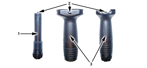
Figure 2-17. Vertical pistol grip.
The Insight rail grabber (Figure 2-18) and the Picatinny rail grabber (Figure 2-20) were designed to mount accessories onto the M16A4 and M4-series weapons. Each rail grabber has proven its ability to retain zero when installed and tightened properly. Both rail grabbers attach accessories on the upper receiver and on all four sides of the RAS. Once zeroed the rail grabbers can be removed from the weapon and will retain zero as long as the rail grabber is not separated from the accessory and is remounted on the exact same notch it was zeroed on. If the accessory and rail grabber is reinstalled on a different notch, or the rail grabber is separated from the accessory, they must be rezeroed. A one-time retightening of the rail grabber and accessory is recommended after the first three rounds are fired to fully seat both. Details specific to each rail grabber are outlined in the following paragraphs.
|
NOTE: |
The bottom rail will not retain zero. |
a. Insight Rail Grabber (Figure 2-18). The Insight rail grabber is used to install the AN/PEQ-2A and AN/PAQ-4B/C. This rail grabber must fully rest on the RAS in order to retain zero. The locking clamp (1) must grasp the RAS, and the screw that tightens the rail grabber must be tightened with a field tool such as a multipurpose tool.
(1) Both of the holes (2) located in the top of the rail grabber can be used to mount accessories, but the hole closest to the muzzle must be used. This ensures the majority of the rail grabber is supporting the accessory being mounted to prevent damage to the accessory.
(2) The rail grabber can be mounted where the tightening screw (3) is on either the left or right side (when top mounted) or top or bottom (when left side mounted) so it does not interfere with the operation of the weapon.
(3) Unless command-directed, all devices in a unit do not have to be mounted in the same location as long as the individual users record or mark the mounting location on their weapon to avoid unnecessary rezeroing. (Some examples of marking techniques are paint markers and grease pencils.)
(4) Even if the rail grabber is resting entirely on the RAS, accessories should not make contact with the front sight assembly or the collar of the barrel. The vibrations that occur during firing will interfere with the rail grabber's and accessory's zero retention capabilities.
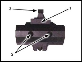
Figure 2-18. Insight rail grabber.
b. MILES Training Extender for the Insight Rail Grabber (Figure 2-19). The purpose of the training extender is to elevate the accessory above the MILES laser during force-on-force training. The extender is installed by using the thumbscrew (1) to hand tighten the extender into the mounting hole closest to the muzzle on the Insight rail grabber. Once the extender is installed, the accessory is installed on top of the extender and tightened. The training extender is only used when the Insight rail grabber is top mounted.
|
NOTE: |
TheAN/PEQ-2A and AN/PAQ-4B/C must be zeroed before and after using the MILES training extender. |
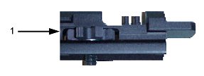
Figure 2-19. Insight rail grabber MILES training extender.
c. Picatinny Rail Grabber (Figure 2-20). The Picatinny rail grabber must fully rest on the RAS in order to retain zero. The locking clamp must grasp the RAS and the torque-limiting knob (1) that tightens the rail grabber must be hand tightened until it clicks two times.
(1) Both of the holes located in the top of the rail grabber (1) can be used to mount accessories, but the hole closest to the muzzle must be used. This ensures the majority of the rail grabber is supporting the accessory being mounted to prevent damage to the accessory. It also allows the torque-limiting knob (2) to be mounted on either the left or right side (when top mounted) or top or bottom (when side mounted) to ensure the torque-limiting knob does not interfere with the operation of the weapon.
(2) Unless command-directed, all devices in a unit do not have to be mounted in the same location as long as the individual users record or mark the mounting location on their weapon to avoid unnecessary zeroing. (Some examples of marking techniques are paint markers and grease pencils.)
(3) Even if the rail grabber is resting entirely on the RAS, accessories should not make contact with the front sight assembly or the collar of the barrel. The vibrations that occur during firing will interfere with the rail grabber's and accessory's zero retention capabilities.
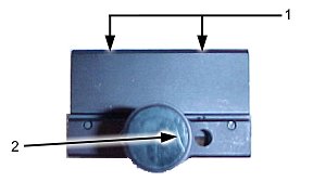
Figure 2-20. Picatinny rail grabber.
The backup iron sight (BIS) (Figure 2-21) is a semi-permanent flip up iron sight, equipped with a rail-grabbing base. It is intended to remain on the MWS while the M68 close combat optic (CCO) reflex sight is used as the primary means of day fire control. If the M68 fails, the prezeroed BIS can be flipped up and used to continue the mission. The BIS should only be removed by the armorer and remains on the MWS at all the times unless the carrying handle/sight is installed.
a. The BIS is installed by the armorer on the first notch of the integrated rail nearest the charging handle. The flip-up sight collapses towards the firer out of the way and can be used while the M68 is mounted. The BIS provides a backup capability effective out to at least 600 meters and can be installed on the M16A4 and M4-series weapons. Before installing the BIS, remove all rail covers/heat shields from the top except one 4-, 5-, or 6-rib shield. The remaining rail cover/heat shield can be positioned to accommodate accessories and protect the nonfiring hand when the barrel is hot.
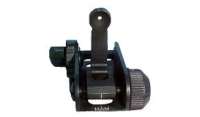
Figure 2-21. Backup iron sight.
b. Once installed and zeroed, the BIS should be left in the stowed position for best durability and minimal interference unless its use is eminent (Figure 2-22). It provides a sighting capability when all other accessories have been removed, and it can be used to establish approximate zeros for other sighting components without requiring live fire. Zeros established using this method are only effective to approximately 20 meters and should be refined by a live-fire zero.
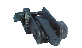
Figure 2-22. BIS in the stowed position.
The M68, close-combat optic (CCO) is a reflex (nontelescopic) sight (Figure 2-23). It uses a red dot aiming point and is designed for the "two-eyes-open" method of sighting. The M68 can be shot with one eye open as well. The dot follows the horizontal and vertical movement of the gunner's eye while remaining fixed on the target. A one-time retightening of the torque-limiting knob is recommended after the first three rounds are fired to fully seat the M68. No centering or focusing is required beyond 50 meters.

Figure 2-23. M68, close-combat optic.
a. M16A1/A2/A3 Rifle (Figure 2-24). The M68 mounts on the M16 mounting bracket (1) that attaches to the carrying handle on the M16A1/A2/A3. The half-moon spacer should not be installed but, if installed, it will not hinder firing performance. Firmly hand-tighten the bracket (1), O-ring (2), and machine screw (3). Align the locking bar (4) under the M68 with the notch in the rail ensuring the rotary switch (5) is facing the firer. Tighten the torque-limiting knob (not shown here) until it clicks two times.
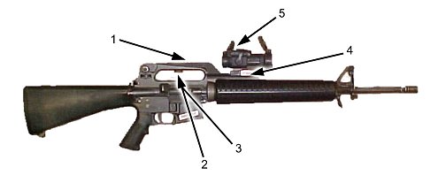
Figure 2-24. Mounting the M68 to the M16A1/A2/A3.
b. M16A4 and M4-Series Weapons (Figure 2-25). The M68 mounts directly to the integrated rail on top of the M16A4 and M4-series weapons (in place of the carrying handle). The half-moon spacer (1) should be installed to raise the M68 above the front sight post but the M68 can still be fired without the spacer. The soldier's preference dictates exactly which notch the M68 is mounted to. Although any notch is acceptable, testing has shown that the farther away the M68 is from the soldier's eyes, the better his field of view. Remove the carrying handle, align the locking bar with a notch, and tighten the torque-limiting knob until it clicks twice. If the M68 is remounted onto the same notch, it will retain zero.
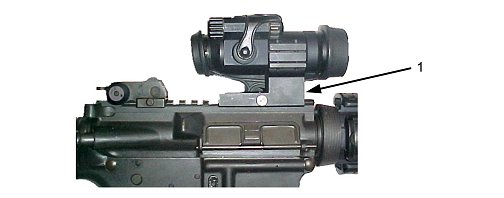
Figure 2-25. M68 mounted on the M16A4/M4-series weapons.
c. M16A4 and M4-Series Weapons with M68 and AN/PVS-14 (Figure 2-26). This combination is an effective passive means of engaging targets during hours of limited visibility. The brightness knob on the M68 should be on the lowest setting that presents the red dot clearly when viewed through the AN/PVS-14. The soldier must consider the following factors:
Remove the carrying handle and mount the M68 (1) by tightening the thumbscrew clamping knob. Mount the AN/PVS-14 (2) where the best field of view is achieved. Once the preferred location for the M68 is located, the M68 must be zeroed to that notch (if different from the notch the M68 was previously zeroed on). (For further information on the M68, refer to TM 9-1240-413-12&P and TM 11-5855-306-10 for the AN/PVS-14).
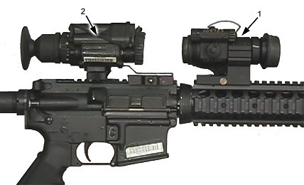
Figure 2-26. Mounting the M68/AN/PVS-14 combination on an MWS.
The AN/PAQ-4B/C infrared aiming light (Figure 2-27) projects an infrared laser beam that cannot be seen with the eye but can be seen with night vision devices. This aiming light works with the AN/PVS-7-series goggles and the AN/PVS-14. The AN/PAQ-4B/C mounts on various M16-/M4-series weapons with mounting brackets or rail grabbers.
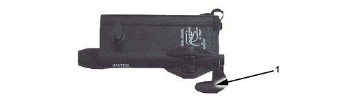
Figure 2-27. AN/PAQ-4B/C infrared aiming light.
a. M16A1/A2/A3 Rifle (Figure 2-28). The armorer must install the bracket assembly (1). The switch lever shroud (2) is aligned with the notches on the mounting rail (3). Lower the on/off switch. The AN/PAQ-4B/C (4) is then aligned with the notches on the switch lever shroud and hand tightened using the thumbscrew (5). Tool tightening is recommended to ensure zero retention if the thumbscrew is metal. The plastic thumbscrew must be hand tightened to avoid breakage. Retightening of the thumbscrew is recommended after a few rounds have been fired to ensure zero retention. The remote switch should be attached to the weapon where it is most convenient for the firer without interfering with the functioning of the weapon or hindering the firer's ability to fire the weapon.
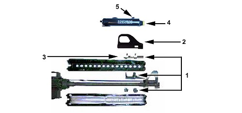
Figure 2-28. Mounting the AN/PAQ-4B/C on the M16A1/A2/A3
and M4 carbine.
b. M16A4/M4 MWS Weapons (Figure 2-29). The Picatinny rail grabber (1) or the insight rail grabber (5) is used to mount the AN/PAQ-4B/C to the RAS. Mount the rail grabber all the way forward on the top or either side of the RAS (2) ensuring it does not extend beyond the end of the RAS. (The AN/PAQ-4B/C will not retain zero if the rail grabber extends beyond the end of the integrated rail when mounted.) Tighten the torque-limiting knob (3) until it clicks twice. Align the thumbscrew (4) on the AN/PAQ-4B/C with the thumbscrew hole in the rail grabber nearest the muzzle. The mounting procedures are identical for the M16A4 and M4-series MWS. The remote switch should be attached to the weapon where it is most convenient for the firer without interfering with the functioning of the weapon or hindering the firers' ability to fire the weapon. If the aiming light and rail grabber are removed as a whole unit and mounted onto the same rail, the system will retain zero. If the rail grabber and AN/PAQ-4B/C are separated, the AN/PAQ-4B/C must be rezeroed to the weapon. (For further information refer to TM 11-5855-301-12&P.)
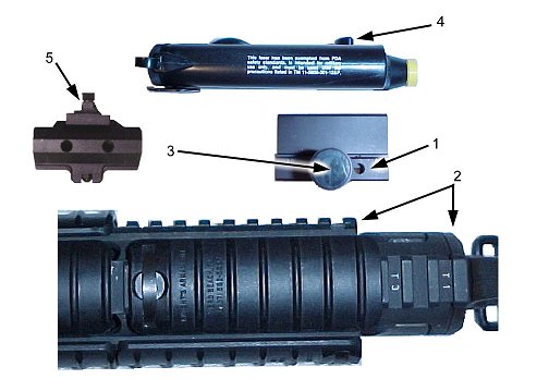
Figure 2-29. Mounting the AN/PAQ-4B/C on the MWS top or left.
The AN/PEQ-2A target pointer/illuminator/aiming light (TPIAL) (Figure 2-30) is a Class IIIb laser that emits a highly collimated beam of infrared light for precise aiming of the weapon as well as a separate infrared illumination beam with adjustable focus to illuminate shadowed areas. The AN/PEQ-2A can be used during force-on-force training in the low power modes only. High power modes can only be used on live-fire ranges exceeding 220 meters. The AN/PEQ-2A is used in conjunction with night vision devices and can be used as either a handheld illuminator/pointer or can be weapon-mounted with included brackets/accessory mounts. The AN/PEQ-2A can be used to accurately direct fire as well as illuminate and designate areas and targets.
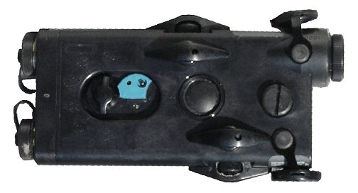
Figure 2-30. AN/PEQ-2A target pointer illuminator/aiming light.
a. M16A1/A2/A3 Rifle and M4 Carbine (Figure 2-31). The armorer must install the bracket assembly (1). The AN/PEQ-2A (2) thumbscrew (3) is then aligned with the hole in the mounting rail (4) nearest the muzzle and tool tightened. The remote switch should be attached to the weapon where it is most convenient for the firer without interfering with the functioning of the weapon or hindering the firer's ability to fire the weapon. Retightening of the rail grabber and thumbscrew is recommended after a few rounds have been fired to ensure zero retention.
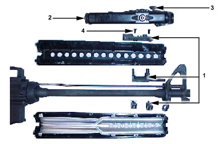
Figure 2-31. Mounting the AN/PEQ-2A to the
M16A1/A2/A3 rifle and M4 carbine.
b. M16A4/M4 MWS Weapons (Figure 2-32). The Picatinny rail grabber (1) or the Insight rail grabber (2) may be used to mount the AN/PEQ-2A to the RAS. Mount the rail grabber all the way forward on the top or either side of the RAS ensuring it does not extend beyond the end of the RAS. (The AN/PEQ-2A will not retain zero if the rail grabber extends beyond the end of the integrated rail when mounted.) Tighten the torque-limiting knob (4) until it clicks twice. If installing the AN/PEQ-2A with the Insight rail grabber you must tool tighten the AN/PEQ-2A and rail grabber or it will come loose. Align the thumbscrew (5) on the AN/PEQ-2A with the hole that is closest to the front sight assembly located on the tope of the rail grabber. The mounting procedures are identical for the M16A4 and M4-series modular weapon systems. If the aiming light and rail grabber are removed as a whole unit and mounted onto the same rail, the system will retain zero. If the rail grabber and AN/PEQ-2A are separated, the AN/PEQ-2A must be rezeroed to the weapon.
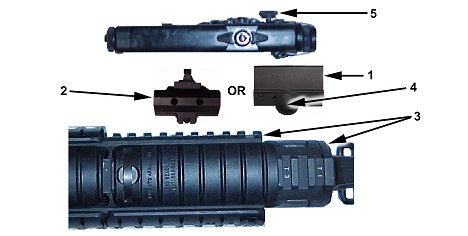
Figure 2-32. Mounting the AN/PEQ-2A on the M16A4 and M4 MWS.
c. M16/M4 MILES Mounting Procedures (Figure 2-33). When conducting MILES training with the Insight rail grabber (1) or bracket assembly (4), the AN/PEQ-2A is attached to the M16-/M4-series weapons using the training extender bracket (2). The training extender is hand tightened by turning the thumb wheel (3) on the training extender clockwise. The training extender bracket is not required when mounting the AN/PEQ-2A onto the side of the MWS. The Picatinny rail grabber does not require the training extender. (For further information refer to TM 11-5855-308-12&P.)
|
NOTE: |
The AN/PEQ-2A and AN/PAQ-4B/C must be zeroed before and after using the MILES training extender. |
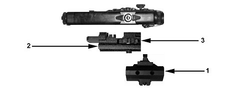
Figure 2-33. MILES training extender bracket installation on
M16-/M4-series weapons.
The AN/PAS-13 (V2) medium thermal weapon sight (MTWS) and the AN/PAS-13 (V3) heavy thermal weapon sight (HTWS) (Figure 2-34) are silent, lightweight, compact, and durable battery-powered infrared imaging sensors that operate with low battery consumption. (Both the MTWS and the HTWS are referred to henceforth as a singular thermal weapon sight [TWS]). The TWS is capable of target acquisition under conditions of limited visibility such as darkness, smoke, fog, dust, and haze. The TWS operates effectively at night and can also be used during the daytime. The TWS is composed of two functional groups: the telescope (1) and the basic sensor (2).

Figure 2-34. HTWS and MTWS models of the thermal weapon sight.
a. M16A1/A2/A3 Rifle (Figure 2-35). The M16A1/A2/A3 weapon bracket (1) is a standard item in the TWS carrying case. The weapon bracket's threaded rod (2) is inserted through the hole in the carrying handle of the M16A1/A2/A3 and secured with the thumb wheel (3). The Picatinny rail grabber (4) on the bottom of the TWS is then aligned with a notch on the bracket, ensuring the TWS is positioned to accommodate an effective firing position once the eyecup (5) is depressed. Ensure the rail grabber fully rests on the bracket when mounting the TWS or the sight will not retain zero.
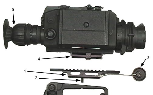
Figure 2-35. Mounting TWS on an M16A1/A2/A3.
b. M16A4/M4-Series Weapons (Figure 2-36). The Picatinny style rail grabber with spacer (1) on the bottom of the TWS is aligned with a notch on the integrated rail (2) of the M16A4/M4-series weapons ensuring the TWS is positioned to accommodate an effective firing position once the eyecup is depressed. The TWS will not retain zero if the rail grabber extends beyond the end of the integrated rail when mounted. Tighten the torque-limiting knob clockwise until it clicks twice. Retightening the rail grabber is recommended after a few rounds have been fired to ensure the sight is fully seated. The mounting procedures are identical for the M16A4 and M4-series MWS.
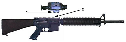
Figure 2-36. Mounting TWS on M16A4/M4-series weapons.
The AN/PVS-4 night vision sight is a portable, battery-operated electro-optical instrument used for observation and aimed fire of weapons at night (Figure 2-37). It amplifies reflected light, such as moonlight, starlight, and sky glow, so that the viewed scene becomes clearly visible to the operator. The AN/PVS-4 does not emit visible or infrared light (except from the eyepiece) that can be detected by the enemy. It can be used on the M16A2 rifle, M4 carbine, and M4 modular weapon system. Mounting brackets are provided for each type of weapon.
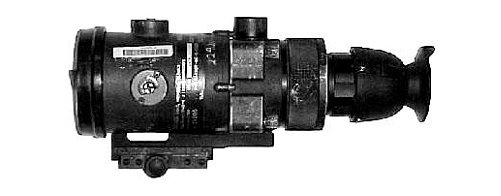
Figure 2-37. AN/PVS-4 night vision sight.
a. M16A2-Series Weapons (Figure 2-38). The AN/PVS-4 is mounted to the carrying handle on the M16A2-series weapons. Position the sight in the groove on the top of the carrying handle and align the threaded hole in the base of the sight-mounting adapter over the hole in the handle. Insert the mounting knob assembly through the hole in the carrying handle and screw it firmly clockwise into the sight-mounting adapter. If difficulty is encountered, turn the sight and the rifle upside down. Place the rifle handle onto the sight-mounting adapter, lining up the hole in the carrying handle with the hole in the sight-mounting adapter. Place the mounting knob assembly through the hole in the carrying handle and screw it clockwise.
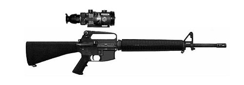
Figure 2-38. AN/PVS-4 on the M16A2-series weapons.
b. M4/M4-MWS-Series Weapons (Figure 2-39). The Picatinny rail grabber with a mounting adapter (1) on the bottom of the AN/PVS-4 is aligned with a notch on the integrated rail (2) of the M4/M4-MWS-series weapons ensuring the AN/PVS-4 is positioned to accommodate an effective firing position once the eyecup is depressed. The AN/PVS-4 will not retain zero if the rail grabber extends beyond the end of the integrated rail when mounted. Tighten the torque-limiting knob clockwise until it clicks twice. Retightening of the rail grabber is recommended after a few rounds have been fired to ensure the sight is fully seated. The mounting procedures are identical for the M4 and M4-MWS-series weapons.
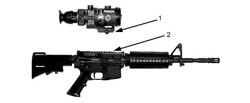
Figure 2-39. AN/PVS-4 on the M4/M4-MWS-series weapon.
The borelight (Figure 2-40) is an eye-safe laser that is used to zero aiming lasers, such as the AN/PAQ-4 or AN/PEQ-2, without a 25-meter confirmation. The borelight has four settings: OFF (the borelight is not in use); GOGGLE (when using NVGs; this mode is selected when using the borelight in a tactical environment); LOW (used during normal operations); and PULSE (used during dry-fire training mode). The borelight will also boresight optics and iron sights to ensure the first shot group hits the 25-meter zero target when zeroing the weapon. The borelight comes with a 5.56-mm, 7.62-mm, .50 caliber, and MK 19 mandrel.

Figure 2-40. Borelight with a 5.56-mm mandrel.
a. Boresighting is conducted at 10 meters with the borelight, weapon, aiming device and a 10-meter offset. Each aiming device and weapon combination has a unique 10-meter offset (Appendix G).
b. Figure 2-41A depicts a 10-meter boresight target and Figure 2-41B depicts a 25-meter zero target. When used properly these offsets will align the aiming device on the selected weapon to engage a target center mass at 300 meters.
(1) The 10-meter boresight target is used in conjunction with the borelight. The 10-meter boresight target is a 1-centimeter grid system with a crosshair and a circle. The crosshair is the aiming point for the aiming device and the circle is the point of impact for the borelight. (Refer to Chapter 8 for a detailed explanation of bore sighting procedures.)
(2) The 25-meter zero target is used when live firing at 25-meters. The 25-meter zero target for the M16- and M4-series weapons is the standard M16A2 zero target with the appropriate strike zone marked on the target (Figure 2-41B). The M4 zero target is only used when zeroing the iron sights on the M4. The aiming point is always center mass of the 300-meter scaled silhouette. The designated strike zone is a 4-by-4 square designating where the rounds should impact when you aim center mass. (Refer to Chapter 8 for a detailed explanation of the 25-meter offset zeroing procedures.)
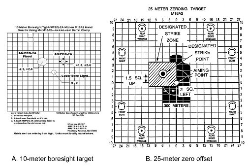
Figure 2-41. 10-meter boresight target and 25-meter zero offset.
This paragraph provides information on different types of standard military ammunition used in the M16-/M4-series weapons (Figure 2-42). Use only authorized ammunition manufactured to U.S. and NATO specifications. (Figures 2-43 through 2-47 show ammunition trajectory data.)
a. Cartridge, 5.56-mm, Ball, M193. The M193 cartridge is a center-fire cartridge with a 55-grain, gilded metal-jacketed, lead alloy core bullet. The M193 round is the standard cartridge for field use with the M16A1 rifle and has no identifying marks (1, Figure 2-42).
b. Cartridge, 5.56-mm, Tracer, M196. (Used in the M16A1 rifle) The M196 cartridge has a red or orange painted tip (2, Figure 2-42). Its main uses are for observation of fire, incendiary effect, and signaling. Soldiers should avoid long-term use of 100 percent tracer rounds, which could cause deposits of incendiary material, or chemical compounds that could damage the barrel. Therefore, when tracer rounds are fired, they are mixed with ball ammunition in a ratio of no greater than one-to-one with a preferred ratio of three or four ball rounds to one tracer round.
c. Cartridge, 5.56-mm, Dummy, M199. (Used in all rifles.) The M199 dummy cartridge is used during dry firing and other training (3, Figure 2-42). This cartridge can be identified by the six grooves along the sides of the case beginning about 1/2 inch from its tip. It contains no propellant or primer. The primer well is open to prevent damage to the firing pin.
d. Cartridge, 5.56-mm, Blank, M200. (Used in all rifles.) The M200 blank cartridge has no projectile. The case mouth is closed with a seven-petal rosette crimp and shows a violet tip (4, Figure 2-42).
e. Cartridge, 5.56-mm, Ball, M855. (Used in the M16A2/3/4 and M4-series weapons.) The M855 cartridge has a 62-grain, gilded metal-jacketed, lead alloy core bullet with a steel penetrator. The primer and case are waterproof. This round is also linked and used in the M249. It has a green tip (5, Figure 2-42). This ammunition should not be used in the M16A1 except under emergency conditions, and only at targets less than 90 meters in distance. (The twist of the M16A1 rifling is not sufficient to stabilize the heavier projectile of the round).
f. Cartridge, 5.56-mm, Tracer, M856. (Used in the M16A2/3/4 and M4-series weapons.) The M856 tracer cartridge has characteristics similar to the M196 tracer with a slightly longer tracer burnout distance. This cartridge has a 63.7-grain bullet. The M856 does not have a steel penetrator. It has a red tip (orange when linked 4 to 1 for the M249) (6, Figure 2-42). This ammunition should not be used in the M16A1 except under emergency conditions, and only at targets less than 90 meters in distance. (The twist of the M16A1 rifling is not sufficient to stabilize the projectile of the heavier ammunition).
g. Cartridge, 5.56-mm Short-Range Training Ammunition (SRTA), M862. (Used in all rifles.) The M862 SRTA (7, Figure 2-42) is designed exclusively for training. It can be used in lieu of service ammunition on indoor ranges and by units that have a limited range fan that does not allow the firing of service ammunition. SRTA ammunition must be used with the M2 training bolt.
(1) Although SRTA closely replicates the trajectory and characteristics of service ammunition out to 25 meters, it should not be used to set battle sight zero of weapons to fire service ammunition. The settings that are placed on the sights for SRTA could be different for service ammunition.
(2) If adequate range facilities are not available for sustainment training, SRTA can be used for any firing exercise of 25 meters or less. This includes the 25-meter scaled silhouette, 25-meter alternate qualification course, and quick-fire training. SRTA can also be used for Urban Operations training. (See Appendix A for use of SRTA in training.)
h. Storage. When storing ammunition in the open is necessary, it must be raised on dunnage at least 6 inches from the ground and protected with a cover, leaving enough space for air circulation. Since moisture and high temperatures adversely affect ammunition and explosives, the following must be adhered to:
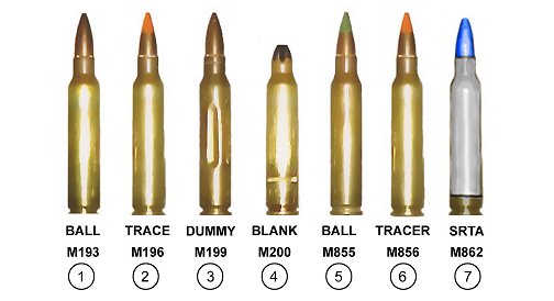
Figure 2-42. Ammunition, 5.56-mm for the M16- and M4-series weapons.
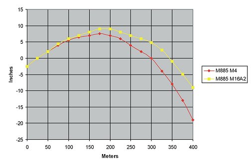
Figure 2-43. M855 drop during 25-meter zeroing
(M16A2 at 8/3+1; M4 at 6/3).
Figure 2-44. Bullet drop of M855 ammunition with M16A2 (8/3).
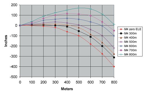
Figure 2-45. Bullet drop of M855 ammunition with M4 (6/3).
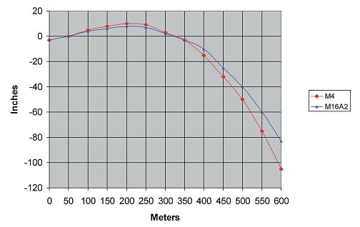
Figure 2-46. M4 carbine and M16A2 rifle bullet
trajectory comparison.
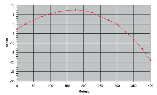
Figure 2-47. Bullet drop of M4/M855 during 25-meter zeroing on 6/3.